商铺名称:扬州市超能电动阀门有限公司
联系人:于淼(先生)
联系手机:
固定电话:
企业邮箱:629449472@qq.com
联系地址:江苏省扬州市维扬区西湖镇俞桥工业园
邮编:225008
联系我时,请说是在泵阀网上看到的,谢谢!
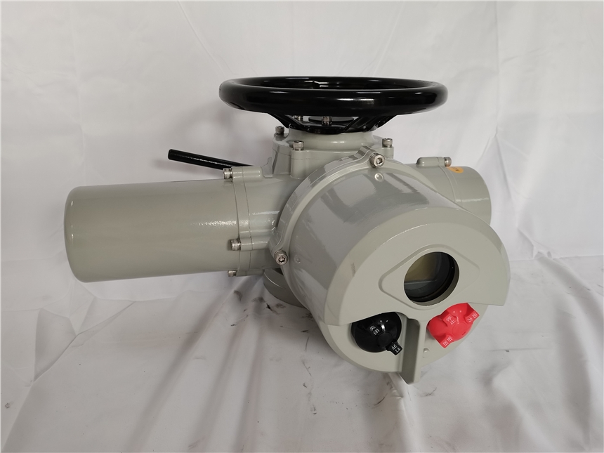
CNZ系列执行器适用于启闭件做直线运动的阀门,如闸阀、截止阀、隔膜阀、柱塞阀、截流阀、水闸门等,可用于明杆 阀,也可用于暗杆阀。可对阀门进行远控、集控和自动控制,广泛应用于电力、冶金、石油、化工、制药、污水处理、农业灌 磨行业。
本系列普通型产品性能符合GB/T24923-2010《普通型阀门电动装置技术条件》的规定;
本系列隔爆型产品性能符合GB3836.1-2010《爆炸性环境第1部分:通用要求》、GB3836.2-2010《爆炸性环境第2部分: 由隔爆夕慌"d"保护的设备》RGB/T24922-2010《隔爆型阀门电动装置技^条件》的规定。
CNZ series actuators, are driving equipment for valves to achieve opening, closing, adjustment and control. This series of actuators have the characteristics of full-featured, reliable performance, advanced control system, small size, light weight, convenient use and maintenance.
CNZ series actuators are suitable for valves with linear movements, such as gate valves, globe valves, diaphragm valves, plunger valves, shut-off valves, water gates, etc., which can be used for bright stem valves and dark stem valves. The valve can be controlled remotely, collectively and automatically. It is widely used in electric power, metallurgy, petro leum, chemical, pharmaceutical, sewage treatment, agricultural irrigation and other industries.
The performance of this series of ordinary products meets the requirements of GB /T24923-2010 "Technical Conditions for Ordinary Valve Electric Devices";
The performance of this series of flameproof products conforms to GB3836.1-2010 "Explosive Environment Part 1: General Requirements", GB3836.2-2010 "Explosive Environment Part 2: Equipment Protected by Flameproof Enclosure" d ""and GB / T24922-2010 "Technical Conditions of Flameproof Valve Electric Device".
二:型号表示方法 / Model representation
CNZ □ □ —□ —□ □
夕卜壳:W表示标准型B表示防爆型
Shell: W means standard type, B means explosion proof type
电压:1表示380V , 2表示220V , 3表泊甥性
Voltage: 1 for 380V 2 for 220V 3 for particularity
I 输出型式:L表示推力型C表示常规转矩型T表示特殊链接尺寸
Output type: I represents thrust type, C represents conventional torque type, T represents special link size
输出睥:阿拉但数字枣示,单位r/min (聲/分)
Output speed: in Arabic numerals, R / min (RPM)
额定输出转矩:用阿拉伯数字表示,单位kgf?m
Rated output torque: expressed in Arabic numerals, unit: KGF ? M
产品功能序列号:3代表普通开关型5代表智能开关型8代表智能调节型
Product function serial number: 3 represents common switch type, 5 represents intelligent switch type, 8 represents intelligent regulation type
产品型式:新款多回转,电动装置
Product type: new multi rotary, electric device 三:产品分类 / Product Categories
按控制方式分:普通型、智能开关型、智能调节型(Profibus现场总线、Modbus现场总线、Hart现场总线、FF 现场总线、Device Net现场总线);
按使用环境分:户外型和防爆型;
按连接方式分:转矩型和推力型;
Divided by control method: Divided by control method: ordinary type, intelligent switch type, intelligent
adjustment type (Profibus fieldbus, Modbus Fieldbus, Hart fieldbus, FF fieldbus,
Device Net fieldbus);
Divided by use environment: Outdoor and explosion-proof;
Divided by connection method: Torque type and thrust type;
四:主要技术指标/ Main Specifications
|
输入信号 Input signal |
4mA~20mA;无源触点 / Passive contact |
|
|
供电电源 Power supply |
常规 Conventional |
三相 /Three phase: AC380V (50Hz) |
|
特殊 Special |
三相 /Three phase: AC660V> AC440V、AC415V (50Hz、60Hz) |
|
|
单相 /Simplex: AC220V、AC110V (50Hz、60Hz) |
||
|
直流 / Direct: DC12V、DC24V> DC48V |
||
|
基本误差限 Basic error limit |
<1% |
|
|
防护等级 Protection class |
IP65、IP68 |
|
|
防爆型等级 Explosion-proof grade |
Exdll BT4; |
|
|
环境温度 Ambient temperature |
-30C~+70'C (可选/Optional: -40C-+100C) |
|
|
环境湿度 Environment humidity |
<95% (25C 时) |
|
|
电机工作制:标配长时电机,F级绝缘 Motor working system: Standard long-term motor, F-class insulation |
||
五:结构 / Structure
阀门电动装置有六个部分组成,电机,减速器,控制机构,手-电动切换机构,手轮部件及电气部分,其传动原理见图一。
The valve electric device is composed of six parts, the motor, reducer, control mechanism, hand-electric switching mechanism, hand wheel components and electrical parts. Its transmission principle is shown in Figure 1.

|

|

|

|

|
转矩 : Torque mechanism
图一传动原理图
Figure 1 Transmission schematic diagram
1. 电动机:采用YDF2-W户夕卜型三相异步电机,该电机为短时工作制,额定持续工作时间为10分钟。
2. 减速器:由一对正齿轮和蜗轮付组成,电动机的动力经减速器传递给输出轴。
3. 控制机构:由转矩控制机构,行程控制机构及可调式开度指示器组成,用以控制阀门的开启和关闭及阀位指示。
(1)转诚制机构(图二一):由曲拐,挡块,凸轮分度盘,支板和微动开关组成,当输出轴受到一定阻转矩后,蜗杆除 礫夕卜,还产生轴向位移,带动曲拐旋转,同时使挡块也产生一个角位移,从而迫近凸轮,使支板上抬。当输出轴上的转矩増大 到预定值时,则支板上抬直至微动开关动作,切断电源,电机停转,以实现对电动装置输出转矩的控制。
1. Motor: ydf2-w outdoor three-phase asynchronous motor is adopted, which is short-time working system and rated continuous working time is 10 minutes.
2. Reducer: it consists of a pair of spur gears and worm gear pairs. The power of the motor is transmitted to the output shaft through the reducer.
3. Control mechanism: it is composed of torque control mechanism, stroke control mechanism and adjust able opening indicator to control the opening and closing of valve and indication of valve position.
(1) Torque control mechanism (Fig. 2.1): it is composed of crank, stop, cam index plate, support plate and microswitch. When the output shaft is subject to certain resistance torque, the worm not only rotates, but also produces axial displacement, which drives the crank to rotate, at the same time, the stop also produces an angular displacement, so as to approach the cam and lift the support plate. When the torque on the output shaft increases to a predetermined value, the support plate is lifted until the microswitch acts, the power supply is cut off, and the motor stops running, so as to realize the control of the output torque of the electric device.

|

|
![]()
|
|
|
|
|
微动开关:The micro switch |
关限位开关:Close limit switch |
调整轴:Adjusting shaft |
顶杆:Ejector pin |
|
支板:Supporting plate |
开限位开关:Open limit switch |
关调整轴:Off adjusting shaft |
关向:Guan Dao |
|
曲拐:Crank |
关向凸轮:Closed cam |
开调整轴:Adjusting shaft |
开向:Open direction |
|
分度盘:Dividing disc |
开向凸轮:Open cam |
|
|
(2)行程控制机构(图二二):由十进位齿轮组,顶杆,凸轮和微动开关组成,简称计数器。其工作原理是由减速箱内
的一主动小齿轮(Z=8 )带动计数器工作。如果计数器按阀门开或关的位置已经调整好,当计数器随输出轴转到预先调整好的 位置(圈数)时,则凸轮将被转动90。,压迫微动开关动作,切断电源,电机停转,壹实现对电动装置行程(圈数)的控制。 为了控制较多转圈数的阀门,可调整凸轮转180。或270。再压迫微动开关动作。
(2) Stroke control mechanism (Fig. 2.2): composed of decimal gear set, ejector pin, cam and microswitch, referred to as counter. The working principle of the counter is driven by a driving pinion (z = 8) in the gearbox. If the counter has been adjusted according to the opening or closing position of the valve, when the counter is turned to the pre adjusted position (number of turns) along with the output shaft, the cam will be turned 90 °, pressing the microswitch action, cutting off the power supply, stopping the motor; and realizing the control of the electric device stroke (num ber of turns). In order to control the valve with more turns, adjust the cam to rotate 180 ° or 270 ° and press the microswitch again.
(3)可调式开度指示器(图三):由减速齿轮组,调节齿轮,阀门开度表盘,凸轮,微动开关,及电位器组成。在现场 调试时,可根据所配阀门开关的圈数,将调节齿轮调整到所需的位置,并与减速齿轮组啮合(在立柱上有所需圈数的数字)。 当阀门在开启或关闭的过程中,开度盘经减速后转动,指示阀门的开关量,指示角度与阀门开关量同步,供远传指示阀门位置 用。
(3) Adjustable opening indicator (Figure 3): it is composed of reduction gear set, adjusting gear, valve opening dial, cam, microswitch and potentiometer. During on-site commissioning, the adjusting gear can be adjusted to the required position according to the number of turns of the valve switch, and it can mesh with the reduction gear set (there is a number of turns required on the column). In the process of opening or closing the valve, the opening plate rotates after slowing down to indicate the on-off value of the valve, and the indicating angle is synchronized with the valve on-off value for remote transmission to indicate the valve position.

|

|
![]() 图四手-电动切换机构
图四手-电动切换机构
Figure 4 Hand electric switching mechanism
|
压簧:Pressure spring |
中间离合器:Intermediate clutch |
蜗轮:Worm gear |
|
切换轴:Switching axis |
切换手柄:Handover handle |
蜗杆:Worm |
|
育立杆:Upright pole |
手轮:Handwheel |
|
手-电动切换机构(图四):为半自动切换,电动转变为手动操作需扳动切换手柄,由手动转变为自动时系自行进行(不 需要扳动切换手柄)。由电动变为手动时,即用人工扳动切换手柄,使输出轴上的中间离合器向上移动,压迫弹簧。当手柄 推到一定位置时之间离合器脱离蜗轮与手动轴爪啮合,则可使手轮上的作用力通过中间离合器传到输出轴上,即成为手动状 态。手动变为电动时自动切换,当电机旋转带动蜗轮转动时直立杆立即倒下,在压簧作用下中间离合器迅速向蜗轮方向移动 ,与手动轴脱开,与蜗轮啮合,则成为电动状态。
Manual electric switching mechanism (Figure 4): it is semi-automatic switching, and the switching handle needs to be pulled for electric to manual operation, and it will be carried out by itself when it is changed from manual to automatic (no need to pull the switching handle). When changing from electric to manual, manually pull the switch handle to make the intermediate clutch on the output shaft move upward and press the spring. When the handle is pushed to a certain position and the clutch disengages from the worm gear and engages with the manual shaft claw, the force on the hand wheel can be transmitted to the output shaft through the intermediate clutch, that is to say, it becomes the manual state. When it is changed from manual to electric, it will switch automatically. When the motor rotates to drive the worm gear; the upright rod will fall down immediately. Under the action of the compression spring, the intermediate clutch will move towards the worm gear quickly, and it will be separated from the manual shaft and meshed with the worm gear; which will become the electric state.
六:外形尺寸 / Dimensions
CNZ05/10/15
CNZ20/30
CNZ45/60


CNZ90/120


CNZ350/500/700/1000
|
寸 Size 型号 Model、^\^ |
H |
H1 |
F |
F1 |
D |
(L) |
L |
(L1) |
L1 |
||
|
我 Ordinary |
锥 Intelligence |
普通 Ordinary |
智能 Intelligence |
||||||||
|
CNZ05/10/15 |
236 |
96 |
334 |
370 |
204 |
240 |
0260 |
392 |
412 |
235 |
255 |
|
CNZ20/30 |
285 |
115 |
372 |
442 |
218 |
288 |
0300 |
449 |
499 |
265 |
315 |
|
CNZ45/60 |
335 |
125 |
510 |
570 |
252 |
322 |
0495 |
/ |
563 |
/ |
357 |
|
CNZ90/120 |
352 |
141 |
517 |
587 |
252 |
322 |
0508 |
577 |
637 |
360 |
420 |
|
CNZ180/250 |
515 |
167 |
524 |
596 |
296 |
368 |
0400 |
/ |
748 |
/ |
470 |
|
CNZ350/500 |
684 |
348 |
524 |
596 |
296 |
368 |
0400 |
/ |
748 |
/ |
470 |
|
CNZ700/1000 |
747 |
411 |
524 |
596 |
296 |
368 |
0400 |
/ |
748 |
/ |
470 |
七:型号及主要技术参数 / Model and main technical parameters
|
型号/规格 Model/ Specification |
输出转矩 Output torque (N.m) |
输出转速 Output 叩 eed (r/min) |
M讓& 仔混融) (Handwheel / Output) |
电机功率(kw) Motor power (380V) |
额定电流(A) Rated current (380V) |
参考重量 Reference weight (kg) |
|
CNZ05 |
50 |
18/24 |
1:1 |
0.12/0.18 |
0.45/0.6 |
15.2 |
|
CNZ10 |
100 |
18/24 |
1:1 |
0.18/0.25 |
0.6/0.85 |
15.8 |
|
CNZ15 |
150 |
18/24 |
1:1 |
0.25/0.37 |
0.85/1.05 |
16.2 |
|
CNZ20 |
200 |
18/24 |
1:1 |
0.37/0.55 |
1.05/1.3 |
24.2 |
|
200 |
36/48 |
1:1 |
0.55/0.75 |
1.3/1.7 |
24.2 |
|
|
CNZ30 |
300 |
18/24 |
1:1 |
0,55/0.75 |
1.3/1.7 |
25.8 |
|
300 |
36/48 |
1:1 |
0.75/0.85 |
1.7/1.85 |
25.8 |
|
|
CNZ45 |
450 |
24/36 |
1:1 |
1.1/1.5 |
2.5/3.2 |
63.2 |
|
CNZ60 |
600 |
24/36 |
1:1 |
1.5/2.2 |
3.2/4.5 |
65.2 |
|
CNZ90 |
900 |
24/36 |
1:1 |
2.2/3.0 |
4.5/6.3 |
68.5 |
|
CNZ120 |
1200 |
24/36 |
1:1 |
3.0/4.0 |
6.3/8.5 |
69.8 |
|
CNZ180 |
1800 |
18/24 |
1:21 |
4 |
8.5 |
120 |
|
CNZ250 |
2500 |
18/24 |
1:21 |
5 |
10.5 |
125 |
|
CNZ 350/500 |
3500/5000 |
8 |
1:60 |
5 |
10.5 |
200 |
|
CNZ 700/1000 |
7000/10000 |
4.5 |
1:107 |
5.5 |
11.2 |
260 |
八:法兰结构与连接尺寸 / Flange structure and connection dimensions
|
|
|
|

|
|
|

|

|
![]()
![]()
![]()

|
![]()

|
![]()
CNZ系列执行器接口尺寸(转矩型) CNZ series actuator interface size(7brque type)
|
执行翱号 Actuator model |
法兰型号 Flange model |
执行器输出接口尺寸明细(转頰型JB2920) Size details of actuator output interface(7brque type JB2920) |
||||||||||
|
D |
D1 |
D2 |
d1 |
d2 |
n-d |
b |
螺孔方向 Screw hole dredion |
h |
hi |
h2 |
||
|
CNZ05 CNZ10 CNZ15 |
2# |
145 |
120 |
90 |
33 |
45 |
4-M10 |
20 |
45。 |
8 |
2 |
5 |
|
2#(I) |
115 |
95 |
75 |
26 |
39 |
4-M8 |
20 |
45。 |
6 |
2 |
5 |
|
|
CNZ20 CNZ30 |
3# |
185 |
160 |
125 |
42 |
58 |
4-M12 |
20 |
45。 |
10 |
2 |
5 |
|
3#⑴ |
145 |
120 |
90 |
30 |
45 |
4-M10 |
20 |
45。 |
8 |
2 |
5 |
|
|
CNZ45 CNZ60 |
4# |
225 |
195 |
150 |
52 |
68 |
4-M16 |
27 |
45。 |
12 |
2 |
5 |
|
CNZ90 CNZ120 |
5# |
275 |
235 |
180 |
62 |
78 |
4-M20 |
30 |
45。 |
14 |
2 |
5 |
|
5#⑴ |
230 |
195 |
150 |
50 |
72 |
4-M16 |
27 |
45。 |
12 |
2 |
5 |
|
|
CNZ180 CNZ250 |
7* |
330 |
285 |
220 |
72 |
98 |
4-M24 |
35 |
45° |
16 |
3 |
6 |
|
CNZ350 CNZ500 |
8# |
380 |
340 |
280 |
83 |
118 |
8-022 |
40 |
22.5° |
20 |
3 |
7 |
|
CNZ700 CNZ1000 |
9# |
430 |
380 |
300 |
93 |
128 |
8-026 |
42 |
22.5° |
22 |
3.5 |
7 |

|
CNZ series actuator interface size(Thrust type)
|
执鶴型号 Actuator model |
法兰型号 Flange model |
执行器融揍口尺寸明细(推力型GB12222) Size details of actuator output interface(Thrust type GB12222) |
||||||||
|
D |
D1 |
D2 |
5梯形堞纹(max) U I Trapezoid thread |
n-d |
b |
缘孔方向 Screw hole dredion |
h |
L |
||
|
CNZ05 CNZ1O CNZ15 |
F1O |
125 |
102 |
70 |
Tr28 |
4-M1O |
16 |
45° |
3 |
40 |
|
CNZ20 CNZ30 |
F14 |
175 |
140 |
100 |
Tr36 |
4-M16 |
25 |
45。 |
4 |
55 |
|
CNZ45 CNZ60 |
F16 |
210 |
165 |
130 |
Tr44 |
4-M20 |
35 |
45。 |
5 |
70 |
|
CNZ90 CNZ120 |
F25 |
300 |
254 |
200 |
Tr60 |
8-M16 |
30 |
45° |
5 |
90 |
|
CNZ180 CNZ250 |
F30 |
350 |
298 |
230 |
Tr70 |
8-M20 |
35 |
22.5° |
5 |
110 |
|
CNZ350 CNZ500 |
F35 |
415 |
356 |
260 |
Tr80 |
8-M30 |
45 |
22.5° |
6 |
150 |
九:电器控制部分 / Electrical control section

|
![]()
![]()
![]()
![]()
![]()
![]()
![]()
![]()
![]()
![]()
|
|
|
|
![]()
|
|
![]()
|
|
|
|
|
|
|
|

|
|
代号 Code name |
名称 Name |
型号 Model |
数量 Number |
备注 Remarks |
代号 Code name |
名称 Name |
型号 Model |
数量 Number |
备注 Remarks |
|
FR |
热継电器 Thermal relay |
|
1 |
用户自备 User self provided |
LSF |
闪光开关 Flash switch |
V-157 |
1 |
|
|
KMOKMC |
交流接触器 AC contactor |
GJ10 |
1 |
用户自备 User self provided |
W1 |
电位器 potentiometer |
WX14-12 |
1 |
|
|
SASOSC |
按钮 Button |
LA11-11D |
3 |
用户自备 User self provided |
M |
电机 Electric machinery |
YDF2-W |
1 |
|
|
TSOTSC |
Torque switch |
DK3-2A |
1 |
|
TH |
榭开关 Thermosensitive switch |
|
1 |
路订货 Special order |
|
LSOLSC |
Travel switch |
HWK-22A |
1 |
|
RT |
空间加热器 Space heater |
|
1 |
跡订货 Special order |

